
I have owned a NAD 522 CD player for around 5 years, and in that time it has served me well. With the advent of upgrading from a 2 channel only system to a full surround system, I decided that a digital connection from the CD player to the receiver was needed. This arose primarily due to the way my receiver (A NAD T752) is configured when it comes to analog inputs and bass management. The T752 passes all analog signals directly to the power amplifier (via the volume control) and completely bypasses any digital circuitry. Bass management is performed only in the digital domain, thus analog feeds were passed full range through to the main speakers, and the sub got only a summed low passed signal (As high as 500Hz no less!). This was not acceptable due to the speaker design I have employed - the speakers and sub have been designed from scratch to work perfectly with the 80Hz crossover option of the T752. Unfortunately, bass management on the T752 is only active on an analog input if a DSP mode is selected. I prefer to listen to stereo recordings in stereo (How they were intended) and thus prefer a direct signal. The only option, therefore, was to connect the CD player to the receiver via a digital connection.
After doing a little research and discovering that many CD players use decoder chips that have a SPDIF output (at TTL levels) already in them, I popped the top and looked at what it would entail. The 522 uses the Sanyo LC78621E DSP chip coupled to a Burr Brown PCM1710U DAC. Luckily, the LC78621E has a digital output pin (pin 56 - DOUT) that turned out to be suitable for the type of circuit I had in mind. The data sheet for the LC78621E decoder chip can be downloaded here.
The DOUT pin is basically the SPDIF output in TTL format (5V high, 0V low) and so a simple buffer circuit (Using a 74HC04 hex inverter) with an output capacitor and a resistive divider to obtain the correct voltages and impedances was all that was needed to get a working digital output.
 Schematic of TTL to SPDIF conversion
I built the circuit on prototype board as it was so simple. Note that the impedances are balanced to approximately obtain the 75 ohm impedance needed for the digital cabling. I obtained the 5V signal line from a jumper (Digital 5V line) and the GND line from the Digital Ground line on another jumper. I hot glued the PCB in place on an unused piece of the PCB.
 SPDIF output circuit glued in place
The SPDIF output was then fed via 75 ohm coax to an RCA connector (Not ideal I know) that was insulated from the case to avoid ground loops and mounted on the rear panel next to the analog outputs.
 75 ohm coax connecting the output circuit to the output RCA socket
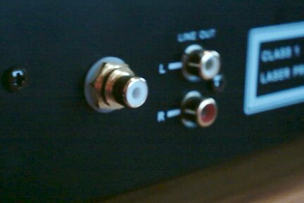
 RCA digital output connector next to analog output jacks
I figured while I had the player open and was playing around that I'd add a 12V input trigger to switch the CD player on, as it had no standby mode, only a main power switch. My T752 receiver has 12V trigger outputs that can be set up to only come on when a particular input (In this case CD) is selected. I thus designed an input circuit to switch the CD player on automatically when it received the 12V signal from the receiver.
I at first thought this would be a relatively simple job of simply hooking up a 12V relay to switch in parallel to the main switch. Thus, when energised with the 12V from the trigger output of the T752, the relay contacts would close, thus turning the CD player on. Unfortunately nothing is that simple, and I quickly discovered that the trigger outputs on the T752 could only output about 20mA or so - not enough to energize the coil of the relay I had selected. (I have since been informed by a NAD technician that new T752's no longer have this limitation.)
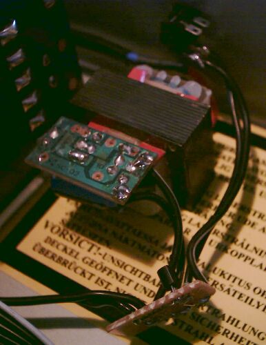
 Relay for switching the CD player on automatically
This is more of a problem than it may seem, as it meant that I needed another 12V source (preferably in the player itself) in order to energize the relay. I couldn't use the main transformer as that is what was switched by the relay, thus I needed either an external 12V source, or I'd have to add another transformer inside the case. Luckily I had a 12V DC power pack from an old phone that was no longer required, so I hacked it up and used the nice small transformer from that.
 Power supply from an old 12C DC adapter
All I needed now was a 3.5mm mono socket for the trigger connection from the NAD and an appropriate circuit to switch the relay using the 12V supply I had created. A quick drilling job yielded a hole for the insulated socket (Important as the chassis is connected to ground) that was soon put in place. A quick tip here is to use some oil (Any oil will do - I used motor oil) as lubrication on the drill bit - it'll go much smoother and won't get as hot.
 New 12V trigger input added to the back panel
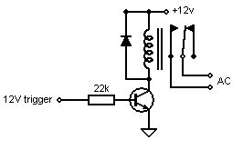
Finally, the switching circuit is extremely simple. All we do is use a resistor to supply just enough current (1mA or so) from the 12V trigger line to the base of an NPN transistor. This is to make sure it is saturated and thus turns on when the trigger line is high. The emitter is tied to ground, and the collector to the relays coil. The other end of the coil is tied to the 12V supply described above. A protection diode is placed across the coil to protect the transistor from the back EMF produced when the coil is (de)energized.
 12V trigger circuit
The modifications all work really well - the CD player turns on automatically when CD is selected as the input mode on the amplifier, and turns off again after the input is switched to something else. The digital input works well, adn the DACs in the T752 receiver certainly sound just as good as the DACs in the CD player, so nothing has been lost sonically speaking. The advantages gained from having full bass management active are great - I am hearing things (particularly in the bass region) that I have never heard before.
Hope you enjoyed the site. For more info, contact me using the link to your left.